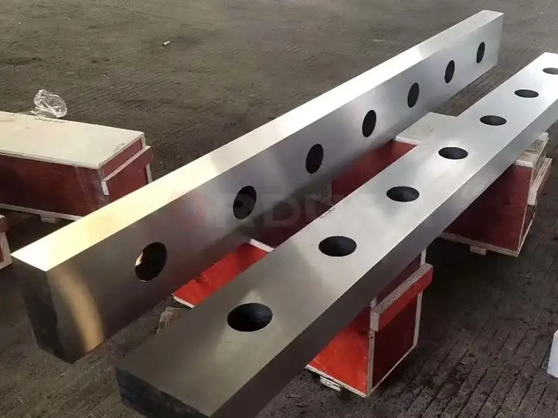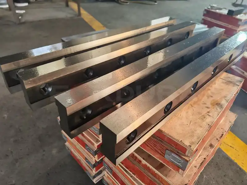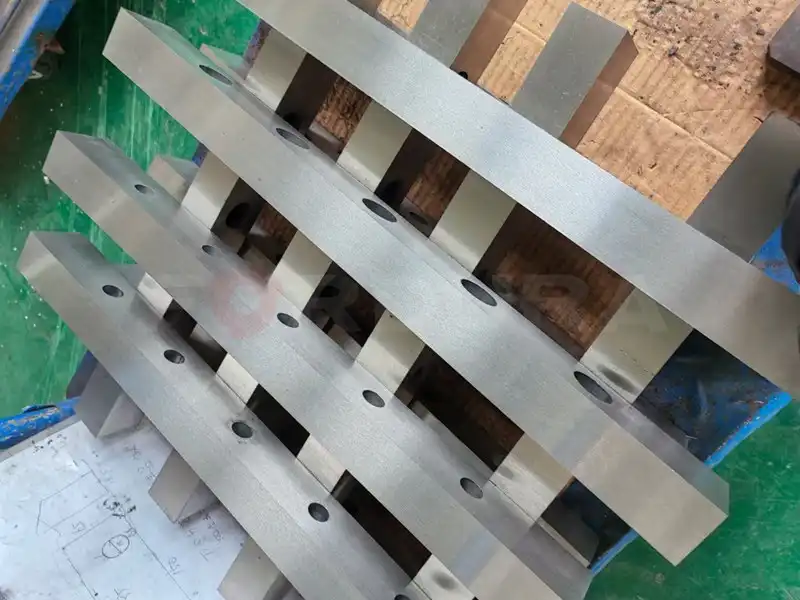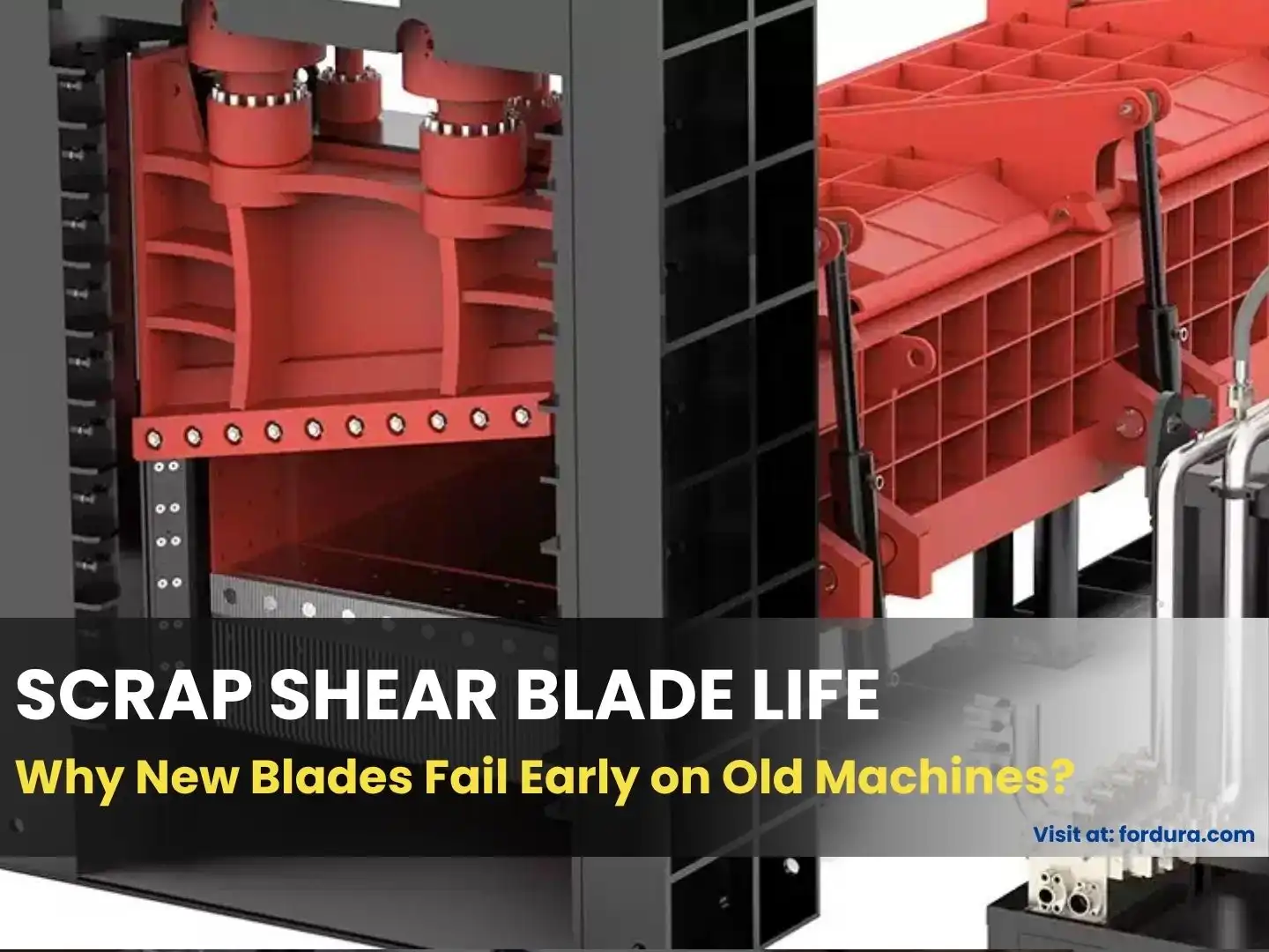
Why does the first blade set on a new scrap shear sometimes run for months, while later replacement blades begin chipping or wearing out much sooner?
The first suspicion is usually blade quality. Perhaps the new steel is not as good. Perhaps the hardness is wrong. Perhaps the replacement blade supplier has reduced quality.
Sometimes those suspicions are justified. But there is another factor that is frequently overlooked:
The replacement blade is new. The machine is not.
When a hydraulic scrap shear leaves the factory, its blade seats, guides, moving blade carrier, fastening system, alignment, and blade clearance are normally commissioned as one cutting system. Years later, a new set of blades may be installed into a machine whose mechanical condition has changed significantly.
Guide surfaces wear. Blade seats develop dents and high spots. Fasteners lose their ability to maintain stable clamping. Wear plates and gibs develop clearance. Alignment shifts. The blade gap that appears acceptable while the machine is stationary may no longer remain consistent when cutting forces act on the moving blade carrier.
That changes what the blade experiences.
Premature scrap shear blade failure is therefore not always a question of finding a harder steel or another blade supplier. Before replacing another set of knives, maintenance teams should determine whether the machine can still provide the mechanical support, alignment, clearance, and clamping conditions that a new blade requires.
Why the First Blade Set Often Lasts Longer?
It is common to hear an operator say:
“The original blades lasted a long time. Every replacement set since then has lasted less.”
That does not automatically prove that the original blades were made from better steel.
When the first blade set begins working in a new hydraulic scrap shear, several favorable conditions usually exist at the same time. The blade seating surfaces are in their original condition. The guide system has little accumulated wear. The moving blade carrier follows its intended path. The upper and lower knives have been aligned during machine commissioning. The fastening system has not yet experienced years of shock loading, repeated removal, tightening, contamination, or thread wear.
Most importantly, the blade does not work independently from these components.
During every cutting stroke, very high forces must pass from the cutting edge through the blade body, mounting surface, blade holder, machine frame, and guidance system. If that load path is stable, the blade is well supported and the cutting forces are distributed much more predictably.
Once the machine accumulates operating hours, the blade itself may still be replaced with a dimensionally correct new part, but the surrounding mechanical system may no longer reproduce the conditions under which the original blade performed.
💡 Manufacturer Insight: Blade Life Is a System Result
A useful way to evaluate scrap shear blade life is to stop thinking of the blade as an isolated consumable.
Blade life is partly a property of the blade, but it is also a result of the cutting system.
Steel grade, hardness, heat treatment, edge geometry, and manufacturing quality all matter. But so do blade-seat contact, guide condition, machine rigidity, working clearance, alignment, fastening stability, feed material, and operating load.
A new replacement blade cannot, by itself, restore a worn machine to its original mechanical condition.
What Changes Before the Second or Third Blade Set?
A scrap shear does not have to look badly worn before machine condition begins influencing blade performance.
Small changes that appear insignificant during visual inspection can become important when hundreds of tons of cutting force act through the blade assembly. A few mechanical conditions deserve particular attention because they directly affect how the blade is supported and how the upper and lower cutting edges interact.
Guide Wear Creates Movement Under Load
The moving blade carrier must follow a controlled path through the cutting stroke.
As guide surfaces, wear plates, gibs, or related guiding components wear, additional movement can develop in the system. What feels like relatively small play during maintenance inspection can matter considerably once cutting forces are applied.
The sequence can look like this:
guide wear → increased carrier movement → changing blade position under load → inconsistent working clearance → localized cutting load → accelerated wear or chipping
This introduces an important distinction between static clearance and dynamic working clearance.
Maintenance personnel may measure blade clearance while the machine is stopped and find a number that appears acceptable. But that measurement only describes the unloaded position of the machine at the point where it was checked.
During an actual cut, the moving blade carrier is subjected to forces that can expose clearance in worn guides or gibs. The blade may shift slightly relative to its unloaded position. As a result, the real cutting gap can become different from the clearance measured during a static inspection.
This does not necessarily mean the entire blade moves dramatically. Even a relatively small positional change can alter where the highest load is concentrated along a long cutting edge.
That is one reason localized chipping should not automatically be interpreted as a metallurgical defect.
If the same area of the machine repeatedly damages different blade sets, the machine position itself becomes an important diagnostic clue.
A Damaged Blade Seat Removes Full-Surface Support
The back of a shear blade needs stable support.
Over years of blade changes and heavy cutting, the seating surface can accumulate:
- dents,
- raised areas,
- fretting marks,
- embedded contamination,
- local deformation,
- corrosion,
- damage from previous blade failures,
- or uneven surfaces left by earlier repairs.
When a new blade is installed over an imperfect seat, tightening the bolts does not necessarily restore proper support.
A blade can look firmly mounted while only part of its back surface is carrying the load.
Under cutting force, unsupported or poorly supported areas of the blade experience different stress than areas sitting firmly against the holder. Instead of the load being transferred uniformly through the blade body into the machine structure, stress becomes concentrated locally.
The mechanical sequence becomes:
poor blade-seat contact → uneven support → localized deflection or stress concentration → abnormal edge loading → increased risk of chipping or cracking
This is particularly important when customers report that a replacement blade repeatedly breaks near the same mounting or cutting position.
Changing from one steel grade to another may temporarily change how the damage appears, but it does not remove the underlying support problem.
Clamping Force Can Become Part of the Failure
Blade bolts do more than keep the knife from falling out of the machine.
Their job is to create sufficient clamping force so that the blade remains firmly seated against its mounting surface while repeated cutting loads pass through the assembly.
If adequate preload is not maintained, microscopic movement can occur between the blade and the holder.
Repeated micro-movement can contribute to:
- fretting at the mounting surface,
- loss of stable blade support,
- progressive bolt loosening,
- changing blade position,
- uneven edge loading,
- and eventually premature blade damage.
This is why simply using a powerful impact wrench is not a complete fastening procedure.
Fastener condition, thread condition, bolt grade, seating surfaces, tightening sequence, and the machine manufacturer’s specified torque or fastening procedure all matter.
Recurring bolt loosening can be a sign of unstable preload or blade movement; see our guide to the scrap hydraulic shear blade fastening system for a deeper explanation of bolt strength, preload, and mounting stability.
For plants experiencing recurring bolt loosening, blade movement, or unexplained chipping around mounting positions, the fastening system should be evaluated as part of the failure investigation rather than treated as a separate maintenance issue.
The Blade Gap May No Longer Stay Consistent
Blade clearance is often discussed as if it were one fixed number.
On a heavily used scrap shear, the more useful question is:
Does the required blade relationship remain consistent across the cutting length and during actual machine movement?
Several conditions can influence that relationship:
- guide or gib wear,
- blade-carrier movement,
- holder deformation,
- blade-seat condition,
- wear-plate condition,
- alignment changes,
- previous repairs,
- or inconsistent blade installation.
For example, clearance may be acceptable at one end of the blade and excessive at another. A carrier may also occupy a slightly different position under load than it does during static measurement.
Too little clearance in a local area can increase contact, rubbing, or impact between cutting edges. Excessive or inconsistent clearance can increase deformation of the scrap before separation and alter the way cutting forces enter the blade.
Neither condition is desirable for stable blade life.
The table below summarizes how seemingly small machine-condition changes can alter what a replacement blade actually experiences.
How Machine Wear Changes What the Blade Experiences
| Machine Condition | Mechanical Change | What the Blade Experiences | Typical Warning Sign |
|---|---|---|---|
| Worn guides, gibs, or wear plates | Blade carrier has more movement | Working clearance varies under load | Localized chipping or inconsistent wear |
| Damaged blade seat | Blade loses uniform backside support | Local stress becomes concentrated | Repeated failure at the same position |
| Unstable bolt preload | Blade can move microscopically | Impact and fretting develop at the mounting interface | Loose bolts, polished contact marks, fretting |
| Alignment change | Knife engagement becomes uneven | One section carries more cutting load | Uneven edge wear along blade length |
| Inconsistent blade clearance | Cutting conditions change along the edge | Local rubbing, impact, or excessive deformation | Chipping, scoring, or abnormal edge rounding |
| Previous holder repair or deformation | Reference geometry changes | New blade no longer sits in the intended position | Difficult alignment or repeated adjustment |
The important point is not that every worn machine will show every symptom.
It is that a replacement blade should be evaluated together with the mechanical conditions controlling its position, support, and load.
Blade Problem or Machine Problem?
This is one of the most important decisions in scrap shear troubleshooting.
If a blade fails early, changing blade suppliers may be appropriate when manufacturing quality is actually the cause. Changing blade material may also be appropriate when the current steel does not have the toughness or wear resistance required by the application.
But neither decision should be made before examining the failure pattern.
The location, repetition, and distribution of the damage can provide valuable clues.
Signs That Point Toward the Machine
Suppose the same blade position chips repeatedly across several replacement sets.
If different batches—or even blades from different suppliers—continue failing in approximately the same machine position, it becomes less likely that random blade quality is the only cause.
The maintenance team should investigate:
- local blade-seat condition,
- guide or gib clearance,
- blade-holder geometry,
- alignment,
- working blade clearance,
- fastening stability,
- and nearby evidence of abnormal contact.
Another warning sign is strongly uneven wear along a long shear blade.
If one section remains relatively healthy while another section rounds, chips, or scores rapidly, the loading environment is probably not uniform. That can indicate an alignment, support, or clearance problem.
Frequent bolt loosening is another clue. Replacing the bolt and continuing production without investigating the underlying movement may allow the same loading condition to damage the next blade.
Signs That May Point Toward the Blade or Material
Machine condition should not become an excuse to dismiss genuine blade problems.
If the blade seats have been verified, alignment is correct, guides are stable, fastening is controlled, and working clearance is within the machine’s required range, yet multiple blade positions wear or chip in a similar manner, the investigation should move toward the blade and application.
Relevant questions then include:
- Is the steel grade appropriate for the scrap being processed?
- Is the hardness suitable for the required balance between wear resistance and toughness?
- Was heat treatment properly controlled?
- Is the edge geometry appropriate?
- Has excessive material been removed during regrinding?
- Has the application changed?
- Is the machine processing heavier, harder, or more contaminated scrap than before?
- Are oversized pieces producing abnormal impact loads?
The objective is not to prove that either the blade or the machine is responsible.
The objective is to identify the variable that actually explains the failure.
Before You Blame the Blade: Read the Failure Pattern
| Failure Pattern | First Area to Investigate | Why It Matters |
| Same machine position chips repeatedly | Blade seat, guide condition, local clearance | The failure follows the machine position |
| Wear is much heavier at one end of the blade | Alignment and support | Cutting load may not be distributed evenly |
| Blade bolts repeatedly loosen | Fastening system and blade movement | Preload may be unstable under repeated impact |
| Different blade suppliers fail in the same location | Machine geometry and support | The common variable is the machine |
| Most cutting edges wear rapidly and uniformly | Material, hardness, application | Blade selection becomes more likely |
| Damage starts after processing abnormal scrap | Operating load and feed condition | Impact may exceed normal application conditions |
| Chipping begins immediately after installation | Seat contact, clearance, alignment, installation | New blade may be entering an incorrect mechanical condition |
This failure-pattern approach can prevent expensive trial-and-error purchasing.
A procurement team that changes steel grades three times without correcting a damaged blade seat may spend more money while learning very little about the actual cause.
Before Installing New Blades: Perform a Three-Step Mechanical Reset
When a replacement blade set is ready for installation, do not treat the job as simply removing the old knives and bolting in the new ones.
The blade change is one of the best opportunities to inspect the mechanical conditions that determine whether the new knives will perform normally.
A practical approach is to restore three areas before production resumes:
the blade seat, the guidance/alignment system, and the fastening/lubrication condition.
⚠️ Maintenance Note: Hydraulic scrap shears contain potentially hazardous stored energy and very heavy moving components. Inspection, adjustment, and blade replacement should follow the machine manufacturer’s lockout, pressure-isolation, lifting, blocking, and maintenance procedures.
Step 1: Restore the Blade Seat
Once the old blade has been removed, the seating surface should be cleaned thoroughly enough that its actual condition can be inspected.
Do not judge the seat through layers of grease, scale, rust, compacted debris, or residue from previous blade failures.
Look for:
- dents,
- raised metal,
- fretting,
- impact marks,
- corrosion,
- cracks,
- deformation,
- embedded particles,
- and irregularities from previous repairs.
The objective is not simply to make the surface look clean.
The objective is to restore reliable contact between the new blade and the supporting surface.
Raised areas can prevent the blade from sitting fully against the holder. Low areas may leave portions of the blade unsupported. Either condition can change how cutting loads enter the blade.
Where repair is necessary, the correct repair method depends on the design and material of the blade holder or seat. Some repairable surfaces may permit controlled weld build-up followed by machining or grinding. Structural or heavily loaded components, however, should not be casually welded because uncontrolled repair can introduce distortion, residual stress, or new geometry errors.
The machine manufacturer’s repair instructions or an appropriate qualified repair procedure should be followed.
The final requirement is simple:
The replacement blade needs a clean, stable, geometrically correct supporting surface.
Step 2: Restore Guide Condition and Blade Alignment
Next, inspect the system that controls blade movement.
Depending on the shear design, this may include:
- guide plates,
- gibs,
- wear strips,
- sliding surfaces,
- replaceable wear components,
- adjustment shims,
- or other blade-carrier guiding mechanisms.
Check for excessive play, unusual wear patterns, damaged guide surfaces, and conditions that allow the moving blade carrier to shift away from its intended path.
If the machine uses adjustable gibs, shims, or replaceable wear plates, adjustments should follow the equipment manufacturer’s procedure. Simply inserting material to remove obvious play is not a substitute for restoring the designed geometry.
After guide condition has been addressed, verify alignment between the moving and stationary blades.
Blade clearance should also be checked at the required positions rather than assuming that one measurement represents the entire cutting length.
For long scrap shear knives, differences from one end to another can be more informative than the value at a single point.
🛠️ Technical Tip: Measure the System, Not Just the Blade
When premature failure appears only in one area, record clearance and contact conditions by position.
A simple maintenance map showing left / center / right blade condition can help reveal whether the failure consistently follows a particular part of the machine.
That information is often much more useful than knowing only the average service life of the blade set.
Step 3: Restore Fastening and Lubrication Discipline
Once the seating and guidance conditions are correct, the blades still need to remain securely in that condition during operation.
Inspect the fastening components before installation.
Look for:
- damaged bolt threads,
- stretched or repeatedly reused fasteners where replacement is required,
- damaged tapped holes,
- poor seating surfaces,
- incorrect bolt grade,
- contamination,
- and evidence that previous blades have moved.
Tightening should follow the specified torque, sequence, lubrication condition, and procedure required by the machine or fastener design.
An impact wrench can be useful as an installation tool, but “tightened with an impact wrench” is not, by itself, a defined preload specification.
Where the maintenance procedure requires a follow-up inspection or re-tightening interval, it should be carried out after the machine has returned to service.
Guide lubrication deserves the same discipline.
The correct lubricant is determined by the machine design and operating conditions. If the equipment manufacturer specifies an NLGI No. 0 grease for a particular guide system, that specification should be followed. It should not be assumed that one grease grade is correct for every hydraulic scrap shear.
The objective of lubrication is not simply to “add grease.”
It is to maintain the intended friction, protection, and wear condition of the guiding surfaces using the correct lubricant and maintenance interval.
Replacement Blade Pre-Installation Checklist
Before closing the machine and returning it to production, maintenance teams should be able to confirm the following:
- ☐ Blade seats are clean and free from raised debris or damaged contact areas.
- ☐ Blade-seat flatness and contact condition have been inspected.
- ☐ Guide, gib, or wear-plate condition has been checked.
- ☐ Excessive blade-carrier play has been corrected.
- ☐ Moving and stationary blades are correctly aligned.
- ☐ Blade clearance has been checked at the required positions.
- ☐ Blade bolts, threads, and seating surfaces are in serviceable condition.
- ☐ Fasteners have been tightened using the specified procedure.
- ☐ Guide surfaces have received the specified lubricant.
- ☐ Abnormal machine movement has been corrected before full-load cutting begins.
This checklist does not replace the machine manufacturer’s maintenance manual. Its purpose is to prevent one common mistake: installing an expensive new blade into a mechanical condition that has not been checked.
What to Check After the New Blades Start Cutting
A successful blade installation is not confirmed simply because the first few cuts are completed.
The early operating period can reveal problems that were difficult to detect while the machine was stationary.
After the machine returns to production, watch for:
- unusual cutting impact,
- abnormal noise,
- fresh edge contact marks,
- unexpected blade movement,
- bolt loosening,
- rapid localized chipping,
- uneven polishing or wear,
- abnormal scoring,
- and changes in guide or carrier behavior.
If a particular section of the blade begins showing damage almost immediately, stop treating the problem as normal break-in wear.
Early localized damage is information.
It may indicate that the blade is contacting improperly, that one area is carrying disproportionate load, or that the carrier position is changing under operating force.
Likewise, a newly installed blade set should not be allowed to run for weeks with repeatedly loosening bolts. Bolt loosening can be the visible symptom of movement elsewhere in the assembly.
Where specified by the machine manufacturer, perform the required post-installation verification of fastening, clearance, guide condition, and lubrication.
This closes the maintenance loop:
inspect → restore → install → operate → verify
Without the final verification step, a machine can begin damaging a new blade immediately while the maintenance team assumes the installation has already been completed successfully.
When Better Blade Steel Helps—and When It Does Not
Material selection matters greatly in scrap shear applications.
High-impact scrap, mixed sections, hard inclusions, heavy plate, structural steel, and demanding cutting cycles place very different requirements on a shear blade than relatively controlled light scrap.
However, better steel cannot correct incorrect machine geometry.
If a blade is rocking on a damaged seat, changing to a more expensive alloy does not flatten the blade holder.
If the moving blade carrier shifts because the guides are worn, increasing blade hardness does not restore guide geometry.
If the blade is repeatedly contacting another edge because working clearance changes during the stroke, greater wear resistance does not remove the contact.
And if insufficient clamping allows the blade to move, a premium steel still experiences abnormal loading.
This is why premature chipping should not automatically trigger a decision such as:
“Use a harder blade next time.”
Hardness is only one property.
Scrap shear blades often need a balance among:
- toughness,
- wear resistance,
- compressive strength,
- resistance to impact damage,
- hardenability,
- dimensional stability,
- and regrinding performance.
Increasing wear resistance at the expense of toughness can even make a material less tolerant of certain impact conditions.
Once the machine condition has been verified and the failure still clearly follows the application rather than a machine position, material selection becomes a much more meaningful decision.
Once machine condition has been verified, our gantry shear blade material guide can help compare steel options according to wear resistance, toughness, and application severity.
For example, a plant experiencing primarily abrasive edge wear may need a different solution from a plant experiencing repeated impact chipping from heavy or contaminated scrap.
The correct sequence is therefore:
verify the machine first → identify the failure mechanism → then optimize the blade material
That approach produces far better procurement information than changing steel grades without knowing why the previous blade failed.
Replace the Blade, Repair the Machine, or Do Both?
The visible cost is usually the replacement blade invoice.
The less visible cost is everything that happens around it:
- shutdown labor,
- blade-change time,
- repeated adjustment,
- lost production,
- damaged bolts,
- damaged blade holders,
- guide repair,
- emergency maintenance,
- and secondary machine damage.
For that reason, the lowest-cost decision is not always “buy the cheapest replacement blade,” nor is it automatically “buy the most expensive blade.”
The best decision depends on what is actually failing.
| Current Condition | More Appropriate Decision |
| Edge has reached normal wear limit and machine condition is stable | Regrind or replace the blade |
| Same blade position repeatedly chips | Inspect machine condition before installing another blade |
| Blade seat is damaged or uneven | Restore the seating surface before replacement |
| Guide or gib play is excessive | Restore guidance before evaluating the next blade set |
| Blade bolts repeatedly loosen | Diagnose fastening and blade movement |
| Machine condition is verified but wear remains excessive | Review blade steel, hardness, and application |
| Blade and mounting components are both damaged | Repair the cutting system before full-load production |
| Application has become more severe | Review both machine condition and blade specification |
This is also where procurement and maintenance teams should communicate more closely.
Procurement may know that blade life has fallen from several months to several weeks, but maintenance may know that a particular guide has been repeatedly adjusted or that one side of the blade seat was repaired after a previous failure.
Those two pieces of information belong in the same purchasing decision.
A blade supplier receiving only the old blade dimensions may be able to manufacture an accurate replacement part.
But if the plant also provides information about:
- failure location,
- processed material,
- previous service life,
- chipping pattern,
- machine condition,
- hardness history,
- regrinding history,
- and operating changes,
the replacement-blade discussion becomes much more useful.
Protect the Cutting System Before Buying the Next Blade Set
A failed blade is easy to see.
Machine deterioration is often less obvious.
That is why a plant can replace several blade sets, blame multiple suppliers, and experiment with harder materials while the same worn guide, damaged seat, unstable fastening condition, or alignment problem remains in the machine.
The most useful question before the next blade purchase is therefore not only:
“Which blade material lasts longest?”
It is also:
“Can the machine still hold this blade in the condition required for it to cut correctly?”
If the answer is uncertain, inspect the blade seat, guidance system, alignment, clearance, and fastening condition before installing another set.
A properly selected blade cannot deliver its expected service life if the machine cannot support and control it properly.
Once the mechanical system has been restored, blade material, heat treatment, hardness, edge geometry, and manufacturing quality can be evaluated on a much fairer basis.
That is the point where a better replacement blade can actually deliver its value.